Automatic Door Simulation
This was the final project completed by me (Michelle Miller) and my partner (Marc Velasquez) for Microprocessor System Design (CEE 345 at Stout) that we took Spring 2016.
Our goal was to simulate an automatic door that would open when an object was nearby. We based this project on Lab 8: Using an IR Sensor, but had to make a few important changes. We used a Freedom Board in the labs and final project for this course.
Starting Out:
We were basing our project off of Lab 8, where we had to program the Freedom Board to light the LEDs when an object was close to the IR sensor. Our first change was to have board control a motor instead of an LED when it receives the IR sensor data. This first step was quite easy. Another change we needed to make was to have the motor stop after a few moments, as real automatic doors would not open/close forever. We would need to construct an H-bridge circuit to control the DC motor, since the board would not provide enough power for most motors. We wanted to have the motor spin both ways, depending on whether it was "opening" or "closing"
Original Schematics:
We originally intended to use an H-Bridge circuit to control the DC motor so that it would be able to spin either way. The H-Bridge schematic we used was very similar to the one below:
 |
| Schematic from a project post on PeterVis.com |
The IR LED circuit was given to us in Lab 8 of the class and is shown below:

The full project was designed as the following:
Problems and Solutions:
The first problem we ran into was with the H-bridge circuit. Initially we believed that it was the code. After testing the code with a small LED circuit, we realized that the problem was the circuit itself. Though we had followed the schematic exactly and had our professor look over everything to be sure, the circuit didn't work. We determined that there was likely a bad part in the circuit. We removed the circuit completely and connected the DC motor directly to the Freedom board. The DC setup worked! Luckily, the DC Motor that we used didn't need very much power and the board's output was sufficient.
The second problem that we encountered was that the IR light was more sensitive than we originally thought. Unless there was no change in distance from the IR sensor (even a human hand makes small changes when held still), the "door" would keep “opening” or “closing”. Again we initially believed that the code was the issue. After verifying that the code was correct, we realized it was the IR sensor itself. We attempted to correct this issue by ignoring small changes in distance and changing the time delay. We used the RGB LED to help us debug the code and know what was going on. The result was not a very accurate door setup and we needed to find another solution. Finally we realized we could create a variable to keep track of the door's state (open or closed). This was a very small change and fixed all the issues we were having. If the door was open, it couldn’t open more. If the door was closed, it couldn’t close again. This rendered small movements irrelevant and stopped pulsing completely.
Final Schematics:
Below is our final setup:
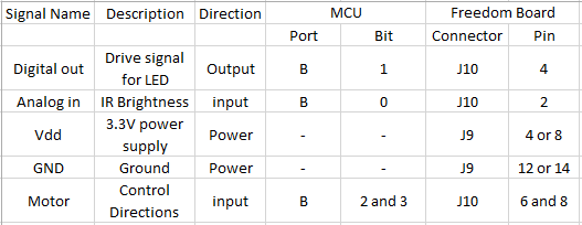
We replaced the H-Bridge circuit with the DC Motor alone. This would not have worked if we had a motor that required more power, but luckily the motor we were using was able to run only with the Freedom Board's output. The following table describes our pin assignments for all components:
Final Result:
The following video is a demo of our project:
Working on this project exposed us to the concepts used in automatic doors. Though real world systems would be more complex, the concepts will remain the same. A big point that we learned was that small changes to the code can make huge differences. We spent hours adding and deleting code, but the final result was only a few added lines. This taught us to look for the simple solution first.